Practical Cross Cut Saw Filing angles
Note: The following article applies only to Western handsaws and backsaws. It does not cover two-man cross-cut saws or other saws that are not sharpened with a triangular saw file (e.g., Japanese saws and Disston's Acme 120). The geometry covered in this article does apply to the vast majority of Western saws made or found and used today.
Before reading this article, you may find it useful to read the article on saw tooth geometry, which defines and explains all of the terminology used below.
Throughout this article, careful attention should be paid to the difference between file and tooth angles. File rake, fleam, and slope
angles are the angles that the file is held at while sharpening a saw (Figure 1). Tooth rake, fleam, and point slope angles
are the actual angles measured on the teeth (Figures 2-4). Although they share names (rake, fleam, and slope), the difference between file and tooth
angles can be dramatic, especially as gullet slope increases.
 Figure 1. File angles, showing the rake, fleam, and slope planes.
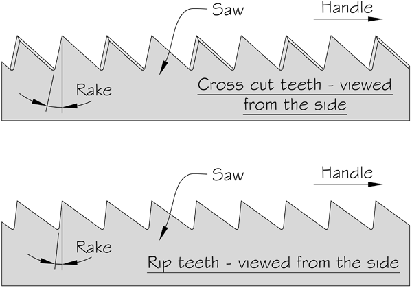
 Figure 2. Tooth rake on rip and cross cut saws.
 Figure 3. Tooth fleam on rip and cross cut saws (no set shown).
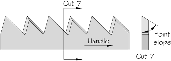
 Figure 4. Tooth point slope on cross cut teeth filed for soft woods, viewed from the side and toe (no set shown).
While there are infinite combinations of angles that may be used to file a cross cut saw, there is a relatively narrow practical range.
But even within this narrow range, tooth geometry and performance can change drastically with even small changes to the
filing angles. Figure 5 covers most of the practical range of cross cut tooth angles that can be created with triangular files.

Figure 5. File angles used to create practical cross cut tooth geometries.
Notes about Figure 5:
The table was created by modeling a triangular saw file and saw plate in SketchUp, then measuring the tooth angles formed by various file rake, fleam, and slope combinations. In all cases, the file rake angle was set first, followed by the file fleam angle. Finally, the file was rotated to create 5°, 13°, or 22° sloped gullets. This mimics the way I sharpen saws, which is to use a rake angle guide (or a RakeMaker) to hold the file rake and fleam angles, while tilting the saw vise to create sloped gullets.
All of the angles are based on the file remaining in contact with both the front and back of the teeth, i.e., not filing the front and back of the teeth separately.
All of the angles are based on filing with the tip of the file pointed towards the toe of the saw if the vise is tilted away from the mechanic, or towards the heel of the saw if the vise is tilted towards the mechanic. I should note that Disston, and many others, recommend filing always toward the toe, which I suspect explains, at least partly, why many old saw vises tilt only away from the filer.
Although some of the combinations shown are not very practical (those outlined by red boxes have very blunt point slopes), they are included to more clearly show patterns and the effects of changing, fleam, and slope.
If you want use the table to create combinations not shown, interpolation and extrapolation should get you fairly close.
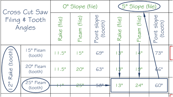
How to read Figure 5:
To create a tooth with:
12° of rake
25° of fleam
60° of point slope
first find the block that contains 12° rake (tooth), then the row within this block that shows 25° of fleam (tooth). Follow this row until reaching 60° of point slope (tooth). From there, it is seen that this tooth geometry is achieved by using the following file angles:
13° of rake
24° of fleam
5° of point slope
It may be helpful to remember that all tooth angles are shown in blue, while all of the file angles are in green. Typically, the rake,
fleam, and point slope angles are chosen (based on the saw's intended use), then the file angles needed to achieve that
geometry are found or calculated. Figure 6 illustrates this.
 Figure 6. Reading the table in Figure 5.
