No other ratcheting brace is more highly sought after than those made under the “Yankee” name. The liberal use of ball bearings, the concealed ratchet, and rugged construction all leave a most favorable impression on the user. Use one that is in good condition, and you will be spoiled for life.
Originally made and sold by The North Bros., these braces feature the mechanical elegance and simplicity for which the firm was justly renowned. When Stanley acquired the company in 1946, they continued to make the brace with only minor changes. This brace is one of those made by Stanley.
Like so many other “Yankee” braces, this one was made expressly for Bell Systems, who valued their rugged, sealed construction. Earlier models are substantially similar. If there is one weak point in these tools, it is that the grease in the sealed ratchets dries out and hardens after a few decades. In many, the grease will be so stiff as to completely freeze the ratchet mechanism. Fortunately, the time and effort needed to clean and regrease the ratchet and pad is not great.
Although the 2101 and 2101A models are far more common than the 2100 and 2100A, there is little difference between the models. To the best of my knowledge, the difference lies in the plating: the 2100’s are chrome plated, while the 2101’s are nickel plated. In 1958, that chrome plating commanded a 20% premium (page 66 of the 1958 Stanley catalog).
A word of warning before starting: while much of the construction remained essentially unchanged over the years, there are some differences. On older braces, I believe that the cladding and bearings on the end handles were peined into place. Disassembly of this requires modification of the brace which may or may not be worth pursuing. If you run into this, or other differences from what I have shown, consider taking pictures of the disassembly process. It takes time to do this, but makes it much easier to put everything back in its proper place.
Without further ado…
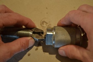
Let’s start with the head. Begin by removing the two or three screws on the underside. The plastic or composition handle is threaded, so after these screws are removed, it will not simply pull off, but will need to be turned counterclockwise (looking at it from the above, as if you were holding it to use). Occasionally, these threads will be a little sticky. If this is the case with yours, hold the collar of the metal cladding in a wooden handscrew or vise (pad the jaws of your vise to prevent damage to the plating).

Unscrew the pad (after removing the screws from the underside).
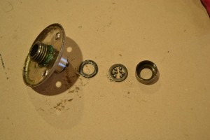
Once the head is removed, you will see a C-clip that holds the cladding and bearings in place. (ab)Use a screwdriver to remove this clip, then lift off the cladding. This is best done with the brace in the upright position so that the now exposed ball bearings don’t make a dash for freedom (hard to blame the little buggers, though – who wouldn’t want to explore the world after toiling away for decades in a confined space?). The bearing cup, races, and bearings can now be removed from the handle and cleaned.

Remove the clip that holds the cladding in place.

With the cladding removed, the ball bearings are exposed. Actually, there is an upper race between the cladding and the bearings, but this often sticks to the cladding when you remove it.

Pull the cup and bearing assembly off the frame.
Most of the parts before cleaning (there are a few bearings that didn’t show up for the class picture).
Reassembly of the pad is simple, so long as it is done in the correct order. The bearing cup goes on first, followed by a bearing race (flat washer). Next, install the grease and bearings. If you give the race and cup a good coating of grease (I use axle grease), the bearings will stay where you stick them. If you managed to lose some of the bearings along the way (there should be 16), take a deep breath and visit a good hardware store and ask for 1/8″ bearings there. If you can’t find them locally, you can order them online. The other bearing race goes on top of the bearings, followed by the cladding and the C-clip to hold everything together. Finally, screw the pad on and reinstall the two or three small screws from below.
Reassembly begins with putting the greased lower race in the cup.

Install the bearings and the upper race.
Replace the bearing assembly on the frame.
The cladding goes on next.

Install the clip to hold everything in place.

Finally, screw the pad back onto the frame, then replace the screws.
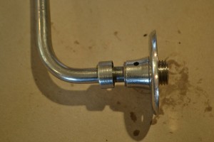
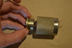
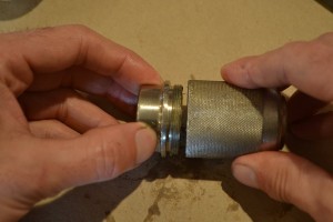
With the pad done, it is time to tear into the shell (the assembly that houses the jaws) and ratchet. Begin by unthreading the shell completely. No tricks here; just turn until it falls off.
Unscrew the shell from the rest fo the brace. This is the easiest part of the entire process, so don’t feel too smug yet.
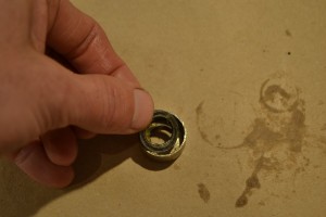
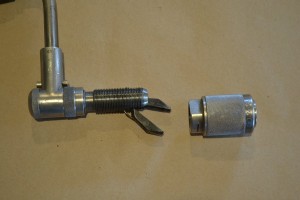
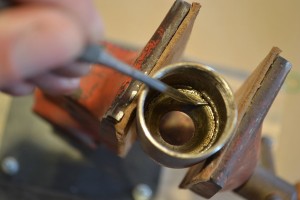
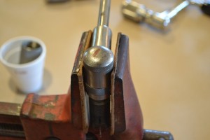
Hold the shell in a handscrew or padded vise jaws and use a wrench or handscrew to remove the end cap. This usually requires little effort. The threads are a standard right hand form.

Hold the body of the shell in padded vise jaws.
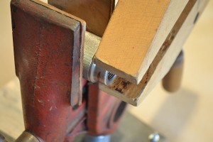
Use a handscrew, monkey wrench, or something similar to remove the end cap.
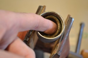
With the cap removed, look down into the shell, where there is an internal spring clip. This clip needs to come out so the cone shaped race and ball bearings can be removed. I use a machinist’s scribe and pick to remove this clip. Patience and persistence are your friends in this step. With the clip removed, the cone race can be removed. Remove carefully, as the ball bearings (there are 31 of them in there) beneath it are no less eager to taste freedom than were those in the head. Remove the bearings and the thrust washer below them.
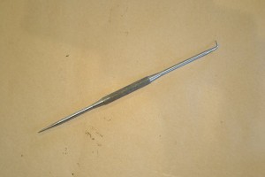
A machinist’s scribe and pick is an invaluable tool for this and many other tasks. Just be careful, or you’ll put your eye out, kid.
Use the pick to remove the internal clip. Expect to spend a few minutes fishing this out.
Remove the cone race.

Remove the clip.

There are 31 ball bearings beneath the cone race. Remove these carefully to avoid losing any of them. You will pay dearly for them if you need to buy them at a hardware store.

With the bearings removed, the lower race can be taken out.
Clean, grease, and reassemble.
After cleaning and greasing, install the lower race, ball bearings, and cone race.

Push the clip back into place. This is a snap compared to removal.
Screw the end cap back into place. Snug it up lightly with a handscrew or wrench.
Squeeze the jaws together, then thread the shell back onto the brace.
Now that you are warmed up, it’s on to the ratchet. This is the most challenging work, but very doable. Pay close attention to how things fit together, and take pictures to help you remember the proper order and orientation.
Begin by removing jaws, then the cap on the end of the ratchet housing. Once again, use wood handscrews or padded jaws to do this. The cap has right hand threads, and usually comes off easily. Use a pick to remove the exposed pawl.

Remove the jaws. I’ve never had much luck removing the spring, and just leave it in place. It is easy to clean around.
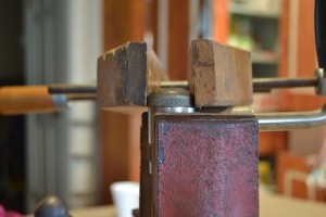
Clamp the ratchet housing in padded jaws.
Use a handscrew to rmove the ratchet cap.
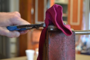
Alternatively, use slip-joint pliers to remove the cap.
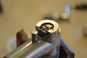
This exposes one of the pawls.

Pull the pawl out.

Close up of the pawl.
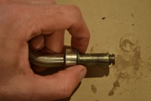
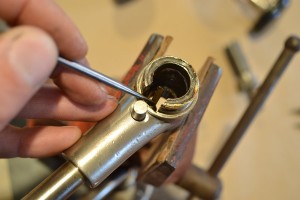
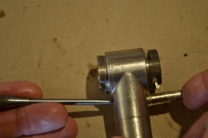
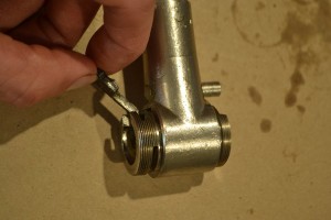
Now turn the brace over to work on the other end of the ratchet housing. Remove the knurled collar using – yes, you guessed it – either a wood handscrew or paded jaws. With this collar unscrewed, use a pick to remove the clip that is now exposed, then lift out the entire shaft and collar.

Flip the brace upside down.
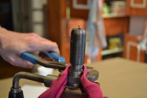
Carefully remove the knurled collar.

Even after the collar is entirely unscrewed, it remains captured by the threaded shaft.
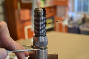
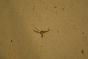
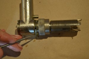
The ratchet and shaft are held in place by a clip.

Remove the clip with a pick or similar implement.
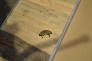
The clip that was removed in the previous step.

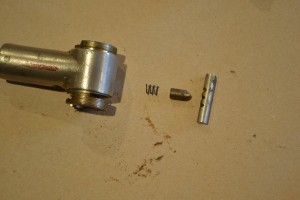
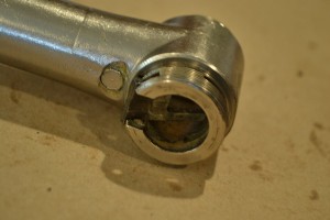
Now the ratchet shaft and collar can slide out of the ratchet housing. There should be no resistance.

This is what you will often find. The green grease has dried out and hardened. With the grooves filled in, the ratchet function does not work.

If a brace has seen heavy use, there may be some burrs on the edges of the ratchet grooves. These can be removed carefully with a fine file.
Now push the ratchet selector down (towards the head) and remove the second pawl. With both pawls removed, the flat spring will slide out.

Press the ratchet selector down.

Because of the way it sits in the housing, the second pawl cannot be pulled straight out. Pivot it first, then pull it out.
With the pawls removed, pull out the flat spring.

The pawls and spring.
The spring shoul have a nice even curve to it. If it does not, it is usually possible to bend it gently. Gently.
Finally, remove the ratchet selector by pushing it in one direction or the other. Once this is out, the spring and pin are free to fall out.

Remove the ratchet selector by pushing or pulling it to one end.

The three grooves are detents for the ratchet selector.
From left to right: spring, pawl, and ratchet selector (this is the proper order for reassembly).
Reassemble after cleaning and greasing everything. Again, I use axle grease here. Reassembly of the pawls and springs is a little tricky. Not complicated, but you will often wish for a third and fourth hand to hold everything in its proper place. Take your time and don’t force anything.
After cleaning and greasing, reassembly starts with the ratchet selector mechanism. After installing the spring and pawl, slide the ratchet selector in. Use a pick or slender tool to hold the pawl back so that the end of the selector can slide past it. The three grooves need to face the pawl.

Use tweezers to put the spring in its place. It is symmetrical, so don’t worry about putting it in backwards.
Install the pawl on the lower end of the housing. It needs to enter at an angle. Be sure that the square-shouldered groove faces the spring (the spring rides in this groove). The two pawls are identical, so don’t worry if you forgot which one came from this end.
The pawl will be pushed out by the spring, but will pivot into place when the shaft is installed.

Slide the shaft into the housing. Make sure the collar is on the shaft, and facing the correct direction.
Replace the retaining clip, then thread the collar back onto the housing. The upper pawl can now be replaced. It will be necessary to use a pick to pry the spring away from the housing to provide clearance for the pawl. Make sure that the spring rides in the square-shouldered groove.

Replace the ratchet housing cap, and snug this and the collar up. Do not overtighten them. Replace the jaws and shell.
And here is the completed brace.

The completed brace. This should outlast all of us.