Milling head/spindle fabrication
The most challenging part of this build is the spindle assembly. Not only does it need to run true, it needs to have a means of vertical or height adjustment. The first concern is easily addressed by careful layout and machining. I went through multiple designs to address the second requirement, with each successive iteration becoming more expensive, costly, and time-consuming to build.
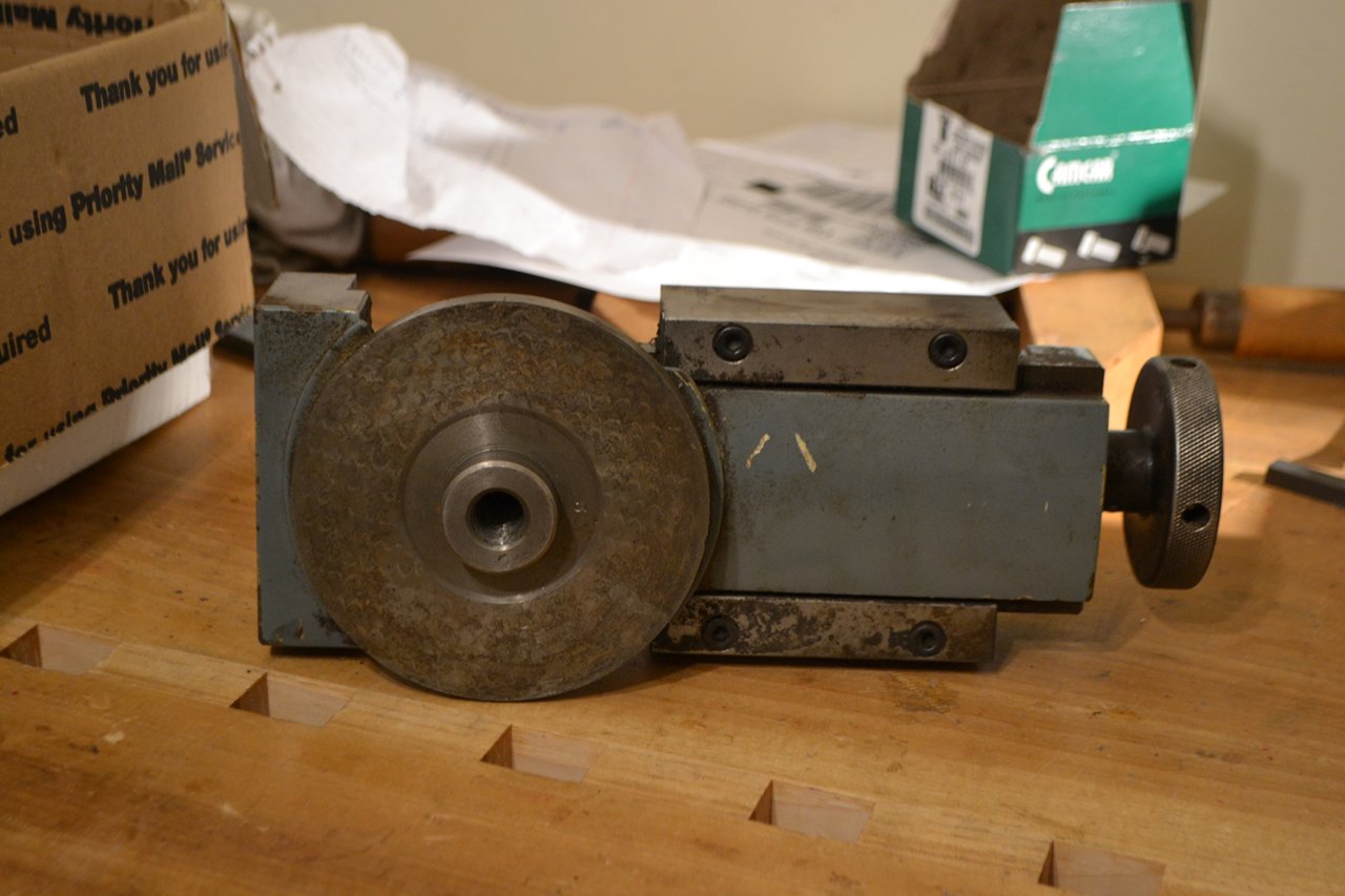
About two months ago, I found a neat solution to the adjustment problem at a local machinery auction. A vise, from some long-forgotten machine, provided about three inches of travel, a nice mounting surface for the milling head, and tank-like construction. A precision tank, no less – there is no perceptible play in it, and backlash of the handle is just a few degrees.
The spindle is a 6″ long ER20 collet chuck. The shaft has a diameter of 20 mm, and runs in a C-shaped mounting block with bearings at each end. In between is a 4 1/4″ diameter flat pulley machined from a piece of solid aluminum. The wide pulley allows vertical travel of the head while the motor remains stationary.

Milling the back and mating surfaces of the milling head.

Milling head components milled and ready for assembly.
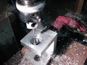
After assembling the C-shaped mounting block, we needed to bore holes in each end for the bearings. Since it is critical that these holes be co-axial, we line bored them from a single setup. This was, I hope, the most complex and time-consuming part of the build.

Indicating the head so that the spindle will be parallel to the back.
Testing the top bearing housing for fit.
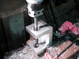
Boring the bottom bearing housing.
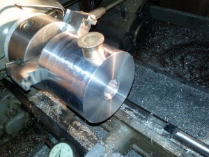
The pulley is straightforward. Since the flat belt must travel up and down on it when the head is moved, there is no crown. I used bronze bearings at both ends of the pulley to avoid an aluminum to steel interface that would make removal difficult. I bored the hole a few thousandths smaller than the flanged bronze bushings, then pressed them in. The ID of the bearings was slightly oversized to begin with, but the press fit compressed them enough to give a perfect slip fit. I still need to drill and tap the pulley for set screws to secure it on the shaft.

Boring the pulley for the shaft and bronze bearings.
Pulley and bearings ready to assemble.

Assembled pulley and bearings.
While the aesthetics leave a little to be desired, time is in short supply for this project. I would dearly love to machine every surface, but for now we are concentrating only on mating and reference surfaces. Everything else will just be sanded or filed by hand to clean it up. In the end, this is a working machine and there is no shame in a little roughness around the edges.